Home/Blog/Piping Flexibility Analysis and BIM: Bridging Static Calculations with 3D Design
Mykola Yarynovskyi
BIM Case Studies
July 12, 2025
Piping Flexibility Analysis and BIM: Bridging Static Calculations with 3D Design
The Gulf's industrial expansion is creating unprecedented challenges for piping system design, particularly in the petrochemical and power generation sectors across the UAE and Saudi Arabia. Traditional approaches to piping flexibility analysis – where stress calculations happen in isolation from 3D design – are becoming a liability in today's fast-paced project environment.
Every day, engineering teams across the Middle East face the same frustrating cycle: design modifications discovered late in the process, costly rework due to thermal expansion conflicts, and coordination nightmares between disciplines. The financial impact is staggering – a single undetected thermal clash in a major petrochemical facility can result in weeks of construction delays and millions in additional costs.
The root cause isn't technical incompetence; it's process fragmentation. When piping stress analysis exists in one software environment and 3D design coordination happens in another, critical information falls through the cracks. Engineers working on high-temperature refineries in Saudi Arabia or complex offshore platforms in the UAE cannot afford this disconnection.
What's needed is a fundamental shift in how we approach piping system design – one that integrates flexibility analysis directly into the BIM workflow from day one. This isn't just about software compatibility; it's about creating a unified design environment where thermal behavior, structural constraints, and spatial coordination work together seamlessly.
The stakes are particularly high in the Middle East, where extreme operating conditions, tight construction schedules, and international quality standards demand precision that traditional fragmented approaches simply cannot deliver. Success requires not just technical expertise, but deep understanding of how integrated workflows can transform project outcomes.
Piping Flexibility Analysis and BIM: Bridging Static Calculations with 3D Design
In today's complex infrastructure and industrial projects, the coordination between piping stress analysis and 3D design is more critical than ever.
Traditionally, piping flexibility analysis – performed in tools like CAESAR II – has been a standalone engineering task.
Meanwhile Building Information Modeling (BIM) has become the backbone of 3D design and coordination. But with tighter timelines, higher performance requirements, and multi-disciplinary collaboration, industry leaders are integrating these processes to improve accuracy, reduce rework, and enhance constructability.
What Is Piping Flexibility Analysis?
Piping flexibility analysis evaluates how a piping system handles stress due to:
Thermal expansion and contraction
Pressure
Vibration
Support constraints
External forces (e.g., seismic loads)
Engineers use tools like CAESAR II, AutoPIPE, or Rohr2 to simulate and ensure that systems conform to standards like ASME B31.1/B31.3.
The result: pipes that are strong enough to operate safely under expected conditions – but also flexible enough to absorb movement without cracking or breaking.
What Role Does BIM Play?
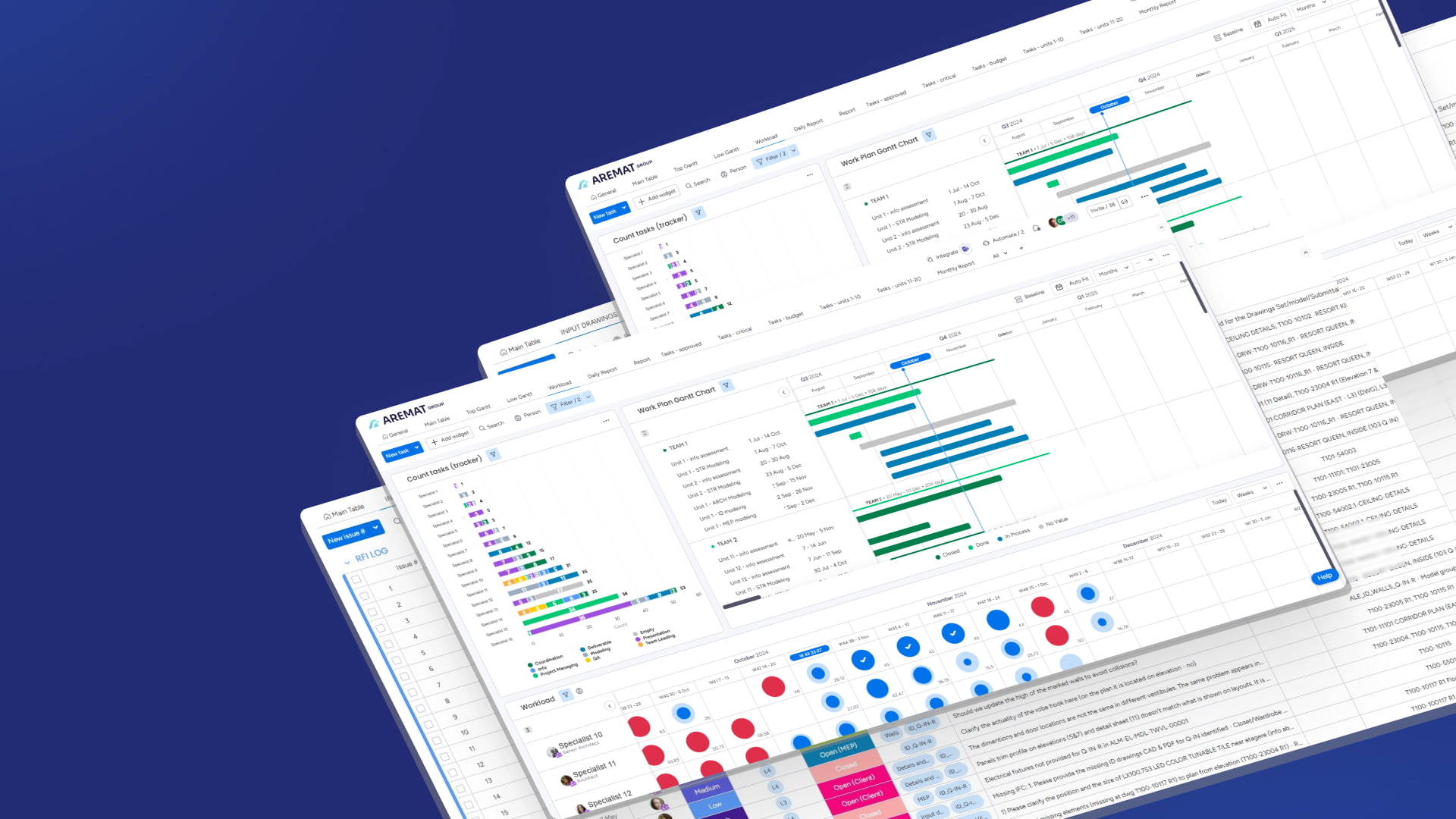
BIM is more than just 3D drafting – it's an intelligent design and data management process. In piping systems, BIM software (like Hexagon CADWorx, Autodesk Revit, Plant 3D, or Bentley OpenPlant) enables:
Accurate 3D layout of pipes and components
Clash detection across disciplines
Integrated material specifications
Support coordination with structural and mechanical systems
This allows for a centralized, coordinated model shared among architects, engineers, and contractors.
Bridging the Two Worlds
Historically, stress analysis and 3D design occurred in silos, often resulting in rework or misaligned designs. However, BIM Leaders now bridge the gap by creating workflows that integrate flexibility analysis results directly into BIM models.
Here's how it works.
Integrated Workflow: From BIM to CAESAR II/AutoPipe and Back
Model in 3D BIM Software. Start by modeling the piping layout in BIM using tools like CADWorx, Plant 3D, Revit, or OpenPlant. Include pipe sizes, routes, fittings, and connections with spatial context.
Export to CAESAR II/AutoPipe Using PCF or ISOGEN. Export the piping data using standardized formats such as PCF (Piping Component File) or ISOGEN, which include geometric and metadata needed for analysis.
Perform Flexibility Analysis. In CAESAR II/AutoPipe, analyze the system for: thermal movement Equipment nozzle loads, anchor point forces, allowable stress checks.
Identify critical support locations, stress concentrations, and necessary expansion loops or joints.
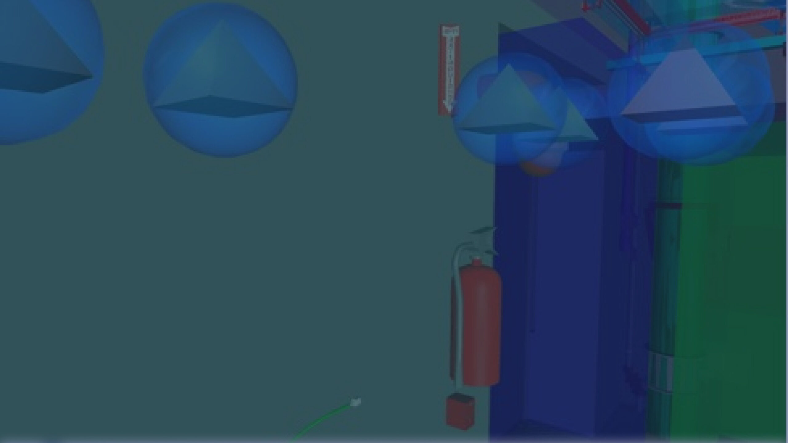
4. Integrate Hot Clash Detection
Go beyond static clash detection by performing Hot Clash Detection—a process that checks for collisions not just in the cold (as-modeled) state, but in the operating (hot or stressed) condition.
Displacement results from CAESAR II/AutoPipe (thermal expansion, sagging, etc.) are imported into the BIM environment
Detect and resolve potential clashes between displaced pipelines and nearby structures, cable trays, ducts, or equipment
This ensures that dynamic behavior is accounted for in spatial coordination, significantly reducing the risk of operational interferences.
5. Import Results into BIM Model
Feed analysis results back into the BIM model. Update:
Pipe routing if stress limits are exceeded
Support types and placement
Displacement values for movement visualization
Special components like spring hangers or flexible joints
Plugins like CAESAR II for CADWorx or OpenPlant + AutoPIPE integrations enable this back-and-forth flow.
6. Re-run Clash Detection and Coordination
With supports and expansion elements added, re-check for interferences using Navisworks or similar tools. Coordinate with other disciplines for changes.
7. Final Documentation & Lifecycle Integration
Generate:
Stress-compliant isometrics
Annotated 3D views showing displacements
BOMs (Bills of Materials) with validated support systems
These models feed into systems like BIM 360 or ProjectWise for construction and facility management.
How BIM Leaders Align Stress Outputs with Design
Standardized Data Exchange
Using PCF or direct software integration ensures that CAESAR II/AutoPipe receives geometrically accurate data, aligned with what's modeled in BIM.
Stress Results Embedded in 3D Models
Support loads, movements, and reaction forces are visualized in the BIM environment to inform routing and placement decisions.
Intelligent Support Libraries
Support families in BIM are enhanced with parameters from engineering: allowable loads, spring constants, movement tolerances—automating smarter placements.
Interoperability Tools
BIM Leaders use platforms that support bi-directional communication (e.g., CADWorx, OpenPlant, Aveva E3D), avoiding manual re-entry and errors.
Digital Twin & Field Use
Stress-compliant BIM models are integrated into digital twins for operations and maintenance. Field teams can visualize thermal movements or stress zones using AR/VR or mobile BIM viewers.
Real-World Applications
Power Plants: High-temp piping routes where thermal growth needs close control
Refineries: Complex networks with tight routing and heavy stress zones
Hospitals & Labs: Cleanroom-grade routing that requires stress tolerance without space to spare
Offshore Platforms: High dynamic loads and tight coordination in multi-discipline environments
Conclusion
The integration of piping flexibility analysis with BIM represents more than a technical upgrade – it's a fundamental shift in how successful engineering teams approach complex industrial projects. The evidence from projects across the Middle East is clear: teams that have mastered this integration consistently deliver superior outcomes in terms of accuracy, schedule adherence, and cost control.
This isn't just about avoiding problems; it's about creating competitive advantage. When your piping systems are designed with thermal behavior and spatial coordination working in perfect harmony, you're not just meeting specifications – you're exceeding them while reducing both timeline and budget pressures.
Why AREMAT Group Leads the Middle East Integration Revolution
At AREMAT Group, we've spent years perfecting the art and science of piping flexibility analysis integration within BIM workflows. Our European engineering team brings a unique combination of theoretical depth and practical experience that's proven invaluable for clients across the UAE, Saudi Arabia, and the broader Gulf region.
What sets us apart isn't just our technical capability – it's our understanding of how integrated workflows translate into measurable business impact. We've seen firsthand how proper integration can eliminate 60-80% of thermal-related design conflicts, reduce construction rework by 40-50%, and compress project schedules by weeks or even months.
Our approach goes beyond software proficiency. We understand that successful integration requires deep knowledge of ASME standards, regional operating conditions, and the specific challenges facing Middle Eastern industrial operators. Whether you're dealing with extreme temperature variations in Saudi Arabian refineries or complex offshore platforms in the UAE, we have the expertise to make integration work in your specific environment.
The Real Cost of Fragmented Workflows
Every day you continue with disconnected piping stress analysis and BIM processes is a day your competitors gain ground. The modern industrial environment demands the precision and efficiency that only integrated workflows can provide. Projects that attempt to bridge these disciplines manually are fighting an uphill battle against teams that have mastered seamless integration.
The financial implications are stark: a single undetected thermal expansion conflict discovered during construction can cost more than implementing proper integration protocols across multiple projects. The question isn't whether you can afford to integrate– it's whether you can afford not to.
Ready to Transform Your Piping Design Process?
AREMAT Group's integrated piping flexibility analysis services don't just solve technical problems – they transform how your engineering teams operate. Our clients consistently report dramatic improvements in design confidence, reduced coordination conflicts, and faster project delivery.
We're not just another engineering service provider. We're your partners in achieving the kind of precision and efficiency that defines successful industrial projects in today's demanding market. Our European engineering standards combined with deep Middle Eastern market understanding create a unique value proposition that our competitors simply cannot match.
Contact AREMAT Group today to discover how our integrated piping flexibility analysis services can accelerate your next industrial project. Let's turn your piping design challenges into competitive advantages.
Frequently Asked Questions (FAQ)
What's the difference between traditional piping stress analysis and BIM-integrated approaches?
Traditional methods require manual data transfer between stress analysis software and 3D design platforms, creating opportunities for errors and requiring multiple iterations. BIM-integrated approaches enable seamless data flow between CAESAR II/AutoPipe and your 3D model, ensuring consistency and reducing rework.
AREMAT Group's European engineering team has perfected these workflows specifically for Middle Eastern industrial conditions, delivering integration that actually works in practice, not just in theory.
How does hot clash detection improve upon standard clash detection?
Standard clash detection only identifies conflicts in the cold, as-modeled state. Hot clash detection accounts for thermal expansion, pressure-induced deformation, and dynamic loads to identify conflicts that would occur during actual operating conditions.
This is particularly critical in Gulf region facilities where extreme temperature variations can cause significant thermal movement that traditional methods miss entirely.
Can existing piping systems be retrofitted with integrated BIM workflows?
Absolutely. AREMAT Group specializes in creating accurate as-built BIM models from existing facilities using laser scanning and then integrating flexibility analysis for retrofit and expansion projects.
Our experience with legacy Middle Eastern industrial facilities has taught us how to work within existing constraints while implementing modern integrated workflows that deliver immediate value.
What software platforms does AREMAT Group use for integrated workflows?
We work with industry-standard platforms including CADWorx, Plant 3D, OpenPlant, and Aveva E3D for BIM, integrated with CAESAR II, AutoPIPE, and other specialized stress analysis tools.
Our European engineering approach emphasizes selecting the right tool combination for each specific project rather than forcing all projects into a single software environment.
How long does it typically take to see ROI from integrated piping workflows?
Most clients see immediate benefits in terms of reduced coordination conflicts and faster design iterations.
Quantifiable ROI typically becomes apparent within the first major project, with 40-50% reductions in thermal-related rework and 20-30% faster design completion times. The time savings alone usually justify the implementation investment within 6-12 months.
Is integrated piping analysis worth it for smaller industrial projects?
The complexity of modern industrial systems means that even smaller projects benefit from integrated workflows. The cost of a single undetected thermal expansion conflict far exceeds the investment in proper integration.
AREMAT Group has developed scalable approaches that make integration cost-effective for projects of all sizes across the Middle East.
How does AREMAT Group ensure compliance with ASME and regional standards?
Our European engineering team brings deep expertise in international standards while maintaining thorough knowledge of regional requirements across the UAE, Saudi Arabia, and the Gulf region.
We ensure that all integrated workflows not only meet ASME B31.1/B31.3 requirements but also comply with local regulations and industry best practices specific to Middle Eastern operating conditions.
Can integrated workflows handle complex multi-discipline coordination?
This is where integrated workflows truly shine. By having piping stress analysis results directly embedded in the BIM environment, coordination with structural, mechanical, and electrical disciplines becomes seamless.
AREMAT Group's approach ensures that all disciplines work from the same accurate, up-to-date model, eliminating the coordination conflicts that plague traditional approaches.
What training and support does AREMAT Group provide for integrated workflows?
We provide comprehensive training that goes beyond software operation to include best practices for integrated design thinking.
Our support extends throughout the project lifecycle, ensuring that your team can confidently implement and maintain integrated workflows. As your European engineering partner, we're committed to knowledge transfer that builds your internal capabilities.
How do integrated workflows improve construction and commissioning phases?
Integrated models provide construction teams with accurate information about thermal behavior, support requirements, and spatial constraints from day one. This eliminates surprises during construction and commissioning, reduces field modifications, and ensures that systems operate as designed.
AREMAT Group's integrated approach has consistently delivered smoother construction processes and faster commissioning for our Middle Eastern clients.

 Mykola Yarynovskyi